Libre MAVID-3M is low cost, low power module targeted primarily for IoT applications. In- built Voice front end and Alexa Voice Service integrated platform extends its capacity to design Voice AI solutions. This document explains how to set up the software development environment for the hardware based on MAVID-3M EVK.
| Icon | Meaning | Description |
|---|---|---|
 |
Note | Provides information good to know |
| caution | Indicates situation that might result in loss of data or hardware damage |
This chapter provides the complete installation procedures followed to set up the MAVID-3M EVK and develop custom applications.
This section provides detailed guideline on how to set up the SDK build environment with default GCC on Linux OS and on Microsoft Windows using MinGW cross-compilation tool.
We recommend using Linux environment for stable build setup.
The default GCC compiler provided in the SDK is based on the 32-bit architecture, Windows/Linux with 64-bit or 32-bit operating system is acceptable.
To Download the MAVID-3M_SDK follow section2.2.
To Install the build environment, follow section 2.3.
To build applications for the MAVID-3M_EVK, Libre provides software libraries as part of software development package.
The SDK package consists of source code for custom application development, supporting tools, documents and mobile application for device configuration.
The MAVID-3M_SDK can be obtained from the Libre GitHub. The MAVID-3M_SDK repository is private and can only be accessed by authorized users. To get access to MAVID-3M_SDK repository, generate the SSH keys and share the public key to SDKsupport@librewireless.com. For more information on SSH Key generation refer to SSH Key Generation Guide.
Once the access is permitted, the SDK can be cloned from the GitHub using the following command:
git clone git@github.com:LibreWireless/MAVID-3_SDK.git
Default GCC compiler provided in the SDK is required to setup the build environment on Linux OS.
Before building the project, verify that the required toolchain is installed for the build environment, as shown in the table:
| Item | Description |
|---|---|
| OS | Linux OS |
| Make | GNU make 3.81 |
| Compiler | Linaro GCC Toolchain for ARM Embedded Processors 4.8.4 |
The following command downloads and installs the basic building tools in Ubuntu:
sudo apt-get install build-essential
A compilation error occurs when building the IoT SDK with the default GCC cross compiler on a 64-bit system without installing the package to support the 32-bit executable binary, as shown below:
/bin/sh: 4: tools/gcc/gcc-arm-none-eabi/bin/arm-none-eabi-gcc: not found
The commands to install the basic build tools and the package for supporting 32-bit binary executable in the Ubuntu are shown below:
sudo dpkg --add-architecture i386
sudo apt-get update
sudo apt-get install libc6-i386
The default installation path of the GCC compiler is <sdk_root>/tools/gcc, and the compiler settings are in the <sdk_root>/.config configuration file.
Setup the BINPATH in the .config file as given below:
BINPATH = $(SOURCE_DIR)/tools/gcc/gcc-arm-none-eabi/bin
If Python is not installed, install Python before proceeding further.
To build the project on Windows OS, install MinGW cross-compiler and integrate ARM GCC toolchain for Windows with the MAVID-3_SDK.
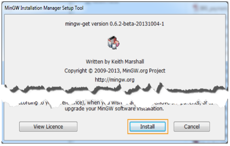
Figure 2.3.2-1: MinGW Installation Manager Setup Tool
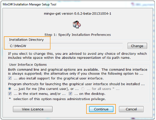
Figure 2.3.2-2: Keep default installation preferences
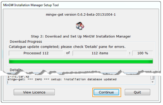
Figure 2.3.2-3: Download and set up MinGW Installation Manager
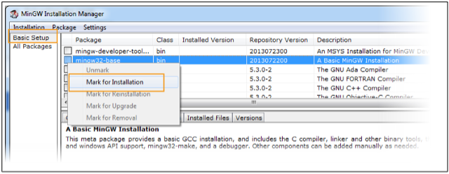
Figure 2.3.2-4: Basic setup on MinGW Installation Manager
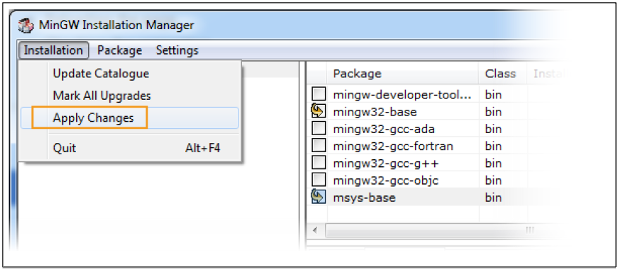
Figure 2.3.2-5: A basic MinGW installation
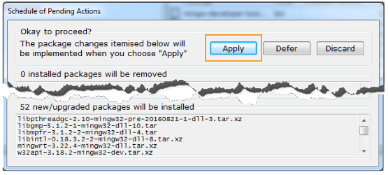
Figure 2.3.2-6: Schedule of pending actions
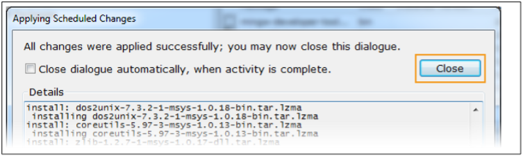
Figure 2.3.2-7: Applying scheduled changes
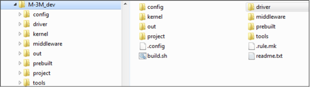
Figure 2.3.2-8: SDK folder structure
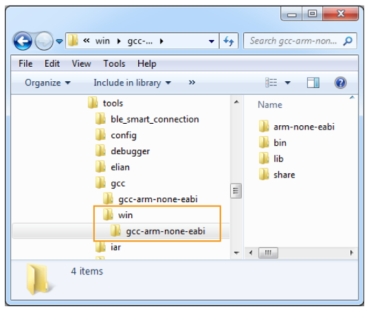
Figure 2.3.2-9: tools/gcc folder structure
arm-none-eabi-gcc.exe: error:
../../../../out/mt2523_hdk/i2c_communication_with_EEPROM_dma/obj/project/mt2523_
hdk/hal_examples/i2c_communication_with_EEPROM_dma/src/system_mt2523.o: No
such file or directory
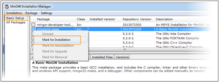
Figure 2.3.3-1: MinGW Installation Manager
Define device manager rules using Udev rules.
The mtk-usb.rules file can be found on <sdk_root>/Flash_tool_files directory, copy that file and paste it to /etc/udev/rules.d/ directory
cp -f mtk-usb.rules /etc/udev/rules.d/mtk-usb.rules
Sign back in or reboot the computer to enable the Udev rules.
In case the device is not detected please try the following.
Build the project using the script at <sdk_root>/build.sh. To find out more about the usage of the script, navigate to the SDK’s root directory and execute the following command:
cd <sdk_root>
./build.sh
Build Project
Usage: ./build.sh <board>
Example:
./build.sh aw7698_evk <project_name>
./build.sh clean (clean folder: out)
./build.sh aw7698_evk clean (clean folder: out/aw7698_evk)
./build.sh aw7698_evk <project_name> clean (clean folder: out/aw7698_evk / <project_name>)
Argument:
-f=<feature makefile> or --feature=<feature makefile>
Replace feature.mk with another makefile. For example,
the feature_example.mk is under project folder, -f=feature_example.mk
will replace feature.mk with feature_example.mk.
-o=<make option> or --option=<make option>
Assign additional make options. For example,
to compile module sequentially, use -o=-j1;
to turn on specific feature in feature makefile, use -o=<feature_name>=y;
to assign more than one options, use -o=<option_1> -o=<option_2>.
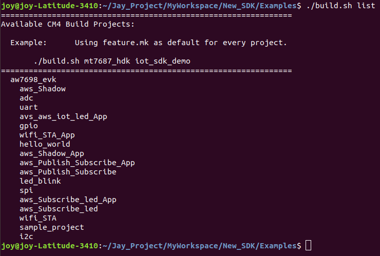
Run the command to show all available boards and projects:
./build.sh list
Output:
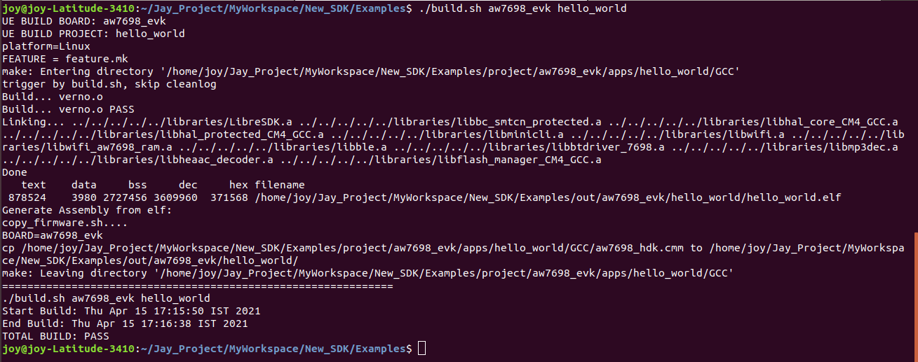
To build a specific project, run the following command:
./build.sh aw7698_evk
The output files will be placed under <sdk_root>/out/ For example, to build a project hello_world, run the following build command: ./build.sh aw7698_evk hello_world ./build.sh aw7698_evk hello_world -f=feature.mk (for customize feature file) The output files will be placed under <sdk_root>/out/aw7698_evk/ hello_world / Output:
Usage:
Example:
./build.sh aw7698_evk hello_world clean
./build.sh aw7698_evk hello_world clean -f=feature.mk
For more details on feature file follow section 2.5.4.
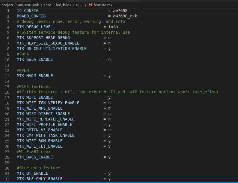
Find the feature.mk file from
<sdk_root>/project/aw7698_evk/apps/<Example_name>/GCC/
Make changes in feature.mk file according to requirements. Also, create multiple feature files and provide the name as a feature_<name>.mk, after creating feature file follow the procedure to build it as shown in section 2.5.
Example feature.mk file:
Tool used for updating the firmware: CODA flash tool
CODA package is provided in <sdk_root>/Flash_tool_files directory.
Now connect MAVID-3M_EVK board to the computer and check under what serial port the board is visible as shown below:
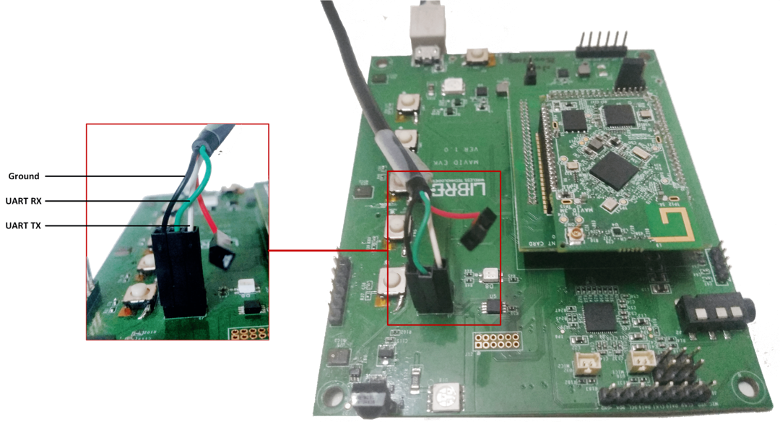
Figure 2.6.1-1: MAVID-3M EVK Setup
Apply the command ‘ls /dev/tty*’ and find the port as a ttyUSBx.
Keep the port name ready as it is required in the next steps.
CODA package for Linux contains below displayed files:
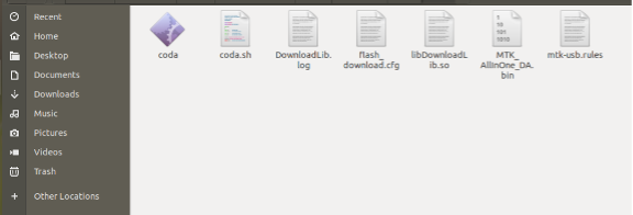
Figure 2.6.2-1: IoT_Falsh_Tool linux
These files will be copied at <sdk_root>/out/<board>/<project>/ directory during build time as the make file contains copy command. If not copied during build, copy the given files from <sdk_root>/Flash_tool_files/ directory to <sdk_root>/out/<board>/<project>/directory.
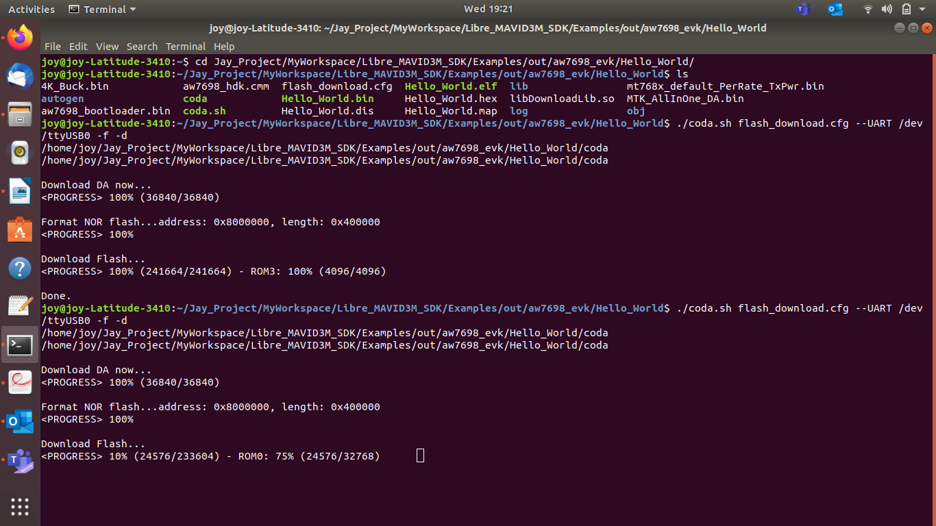
Run the below command:
$ ./coda.sh flash_download.cfg --UART /dev/ttyUSBx -f -d
During flashing, the below output log will be displayed:

If there are no issues by the end of the flash process, the board will reboot and start up the “hello_world” application:
Coda package is part of MAVID-3M_SDK release SDK and can be found under <sdk_root>\tools\FOTA_Packaging_Tool\win\
To install the IoT Flash Tool, copy the package folder to the Windows computer. No further steps are required.
CODA package for windows will contain below given files:
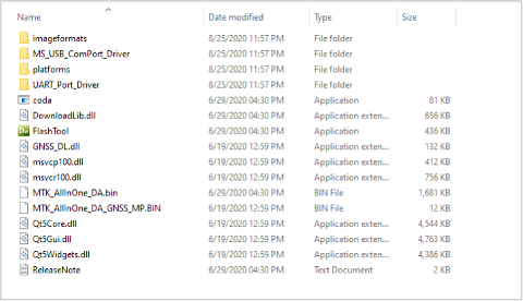
Figure 2.6.3-1: IoT_Flash_Tool contain for windows
The IoT Flash Tool is used to download, format and readback images on the flash memory of the target device.
Run FlashTool.exe from IoT Flash Tool package. (refer Installing IoT Flash Tool)
The main GUI of the tool is shown in the below figure. Each item on the main GUI will be described in detail in the following sections.
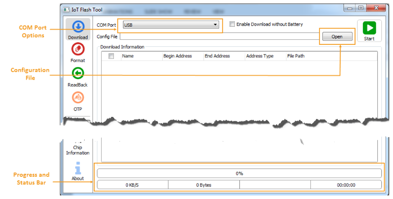
Figure 2.6.3-2: IoT Flash Tool’s main GUI
<sdk_root>\out\<board>\<project>\flash_download.cfg. Download Information will be displayed, including Name, Begin Address, End Address, Address Type and File Path of the firmware binary, as shown in the figure below:
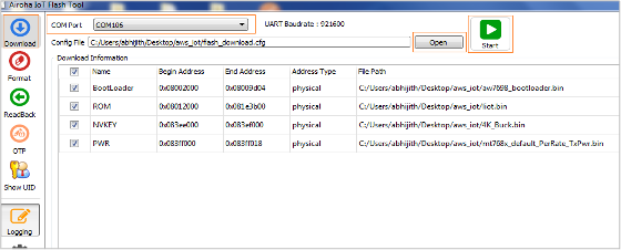
Figure 2.6.3-3: Download the firmware to a target device using UART connection
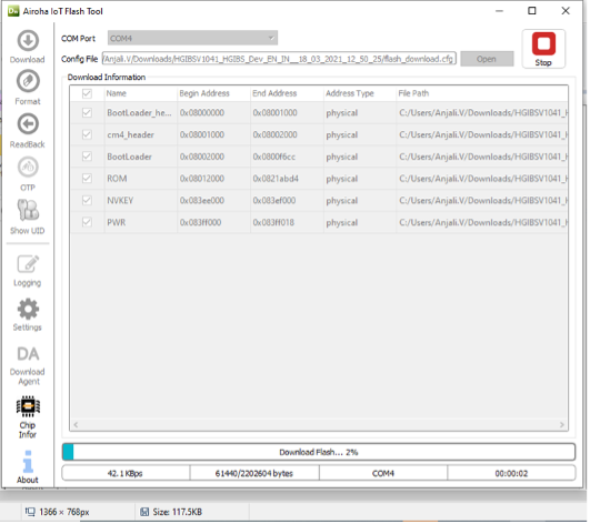
Figure 2.6.3-4: Firmware Flashing Screen
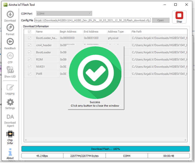
Figure 2.6.3-5: Firmware Flash Success
The status bar is in green color.
The following image displays Erasing flash/program:
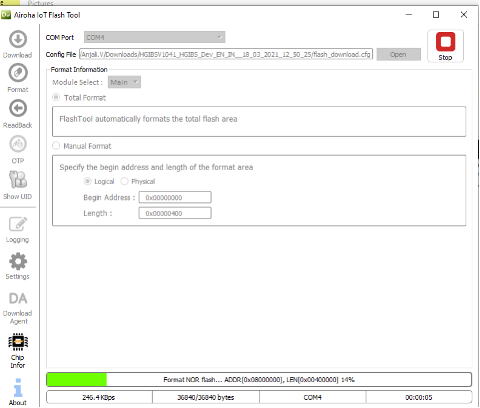
Figure 2.6.3-6: Erasing Flash
To check if project is indeed running, open the terminal like gtk Term and set the credentials.
Example: Teraterm, putty, gtkterm, etc.
Hardware connection for UART cable is displayed below:

Figure 2.7-1: MAVID-3M EVK Setup
| Baud Rate | 115200 |
| Data | 8 bits |
| Parity | None |
| Stop Bits | 1 bit |
| Flow Control | None |
| Enable LF on the serial receive |
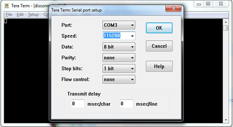
Figure 2.7-2: Serial port configuration
Command Line Interpreter (CLI)
The CLI provides various useful debugging and system status commands.
Enter “?” to view the available commands and explore the options under each section.
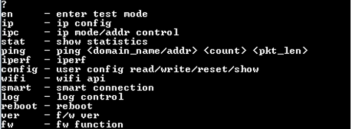
Figure 2.7-3: CLI command screen
User should update MAVID-3M_SDK from time to time, as newer versions fix bugs and provide new features. The simplest way to do the update is to delete the existing MAVID- 3M_SDK folder and follow the initial installation already described in section 2.2.
This project demonstrates the example projects of Peripherals of MAVID-3M_EVK.
MAVID-3M_EVK board contains following user-friendly Peripheral interfaces:
For more details refer MAVID-3M Data Sheet document.
This project demonstrates complete procedure to interface externals with GPIOs of MAVID- 3M_EVK. User can interface the external LEDs with 100ohm resistor or according to LED voltage capacity and perform the task. User can also monitor in digital oscilloscope or in multimeter.
Some external pins are available to perform GPIO operations as listed below:
Use these GPIOs to perform the operations:
GPIO_5 ===> I2C_SCL
GPIO_6 ===> I2C_SDA
GPIO_14 ===> SPI_MISO
GPIO_15 ===> SPI_MOSI
GPIO_16 ===> SPI_CLK
GPIO_17 ===> SPI_CS
Find the GPIO example project at "<sdk_root>/project/aw7698_evk/apps/gpio".
Follow the given steps to customize the project:
Set without_app =1 in main.c.
Initialize CLI task to enable user input CLI command from UART port.
This project demonstrates complete procedure for UART communication of 7698 EVK.
A Universal Asynchronous Receiver/Transmitter (UART) is a hardware feature that handles communication (i.e., timing requirements and data framing) using widely adapted asynchronous serial communication interfaces. A UART provides widely adopted method to realize full-duplex or half-duplex data exchange among different devices.
UART controller is independently configurable with parameters such as baud rate, data bit length, bit ordering, number of stop bits, parity bit, etc. All the controllers are compatible with UART-enabled devices from various manufactures, use that devices to perform UART communication.
Find the UART example project from "<sdk_root>/project/aw7698_evk/apps/uart".
Use hal_uart_config_t structure to configure UART parameters like baud rate, parity bits, stop bits and word length.
hal_uart_config_t uart_config;
uart_config.baudrate = HAL_UART_BAUDRATE_115200;
uart_config.parity = HAL_UART_PARITY_NONE;
uart_config.stop_bit = HAL_UART_STOP_BIT_1;
uart_config.word_length = HAL_UART_WORD_LENGTH_8;
Use Preconfigured UART port HAL_UART_0 for UART communication. This port is also connected for CLI.
Follow the given steps to customize the project:
Set without_app = 1 in main.c.
This project demonstrates complete procedure to interface externals with SPI of 7698 EVK.
SPI is a synchronous, full duplex master-slave-based interface. The data from the master or the slave is synchronized on the rising or falling clock edge. Both master and slave can transmit data at the same time. The SPI interface can be either 3-wire or 4-wire. This section focuses on the popular 4-wire SPI interface.
Serial Peripheral Interface (SPI) is an interface bus commonly used to send data between microcontrollers and small peripherals such as shift registers, sensors, and SD cards. It uses separate clock and data lines, along with a select line to choose the device that the user wishes to talk to.
External pins are available to perform SPI operations as listed below:
GPIO_14 ===> SPI_MISO
GPIO_15 ===> SPI_MOSI
GPIO_16 ===> SPI_CLK
GPIO_17 ===> SPI_CS
Find the SPI example project from "<sdk_root>/project/aw7698_evk/apps/spi".
Use hal_spi_master_config_t structure to configure SPI parameters like bit order slave port, clock frequency, clock phase and clock polarity.
hal_spi_master_config_t SPI_config;
spi_config.bit_order = HAL_SPI_MASTER_LSB_FIRST;
spi_config.slave_port = HAL_SPI_MASTER_SLAVE_0;
spi_config.clock_frequency = 1000000;
spi_config.phase = HAL_SPI_MASTER_CLOCK_PHASE0;
spi_config.polarity = HAL_SPI_MASTER_CLOCK_POLARITY0;
Use hal_spi_master_send_and_receive_config_t structure to configure receive and send parameters like receive data length, send data length, send data buffer and receive data buffer.
spi_send_and_receive_config.receive_length = 2;
spi_send_and_receive_config.send_length = 1;
spi_send_and_receive_config.send_data = &status_cmd;
spi_send_and_receive_config.receive_buffer = status_receive;
Follow the given steps to customize the project:
Set without_app =1 in main.c.
Initialize CLI task to enable user input CLI command from UART port.
This project demonstrates complete procedure to interface externals with I2C of 7698 EVK.
The Inter-Integrated Circuit (I2C) Protocol is a protocol intended to allow multiple "peripheral" digital integrated circuits ("chips") to communicate with one or more "controller" chips. Like the Serial Peripheral Interface (SPI), it is only intended for short distance communications within a single device. It only requires two signal wires to exchange information.
External pins are available to perform I2C operations as listed below:
GPIO_5 ===> I2C_SCL
GPIO_6 ===> I2C_SDA
Find the I2C example project from "<sdk_root>/project/aw7698_evk/apps/i2c".
Use hal_i2c_config_t structure to configure I2C frequency setting:
Hal_i2c_config_t i2c_config;
i2c_config.frequency = HAL_I2C_FREQUENCY_400K;
Follow the given steps to customize the project:
Set without_app =1 in main.c.
Initialize CLI task to enable user input CLI command from UART port.
This project demonstrates complete procedure to interface RGB LED of 7698 EVK.
Use the given preconfigured RGB LED, which is connected with BT chip with GPIOs EX_GPIO_18, EX_GPIO_1 and EX_GPIO_15 to perform led_blink/led_breath operations as listed below:
BSP_LED_0
BSP_LED_1
BSP_LED_2
Find the led_blink example project from "<sdk_root>/project/aw7698_evk/apps/led_blink".
Use bsp_led_config_t structure to configure ON, OFF time and repetition of RGB LED.
Follow the given steps to customize the project:
Set without_app =1 in main.c.
Initialize CLI task to enable user input CLI command from UART port.
For LED control Project call bt_create_task, RGB led is interfaced with BT chip.
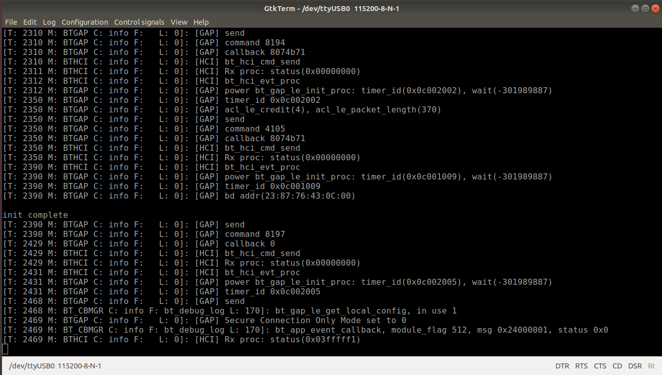
While running the code BT will start and it will display the logs as shown below:
This project demonstrates Wi-Fi configuration of MAVID-3M EVK. The Wi-Fi credentials are configured within the code at compile time or using CLI commands at run time.
The example project is available at "<sdk_root>/project/aw7698_evk/apps/wifi_STA".
#define WIFI_SSID ("ssid")
#define WIFI_PASSWORD ("12345678")
int PRE_CONFIG=1;
int PRE_CONFIG=0;
Initialize CLI task to enable user input CLI command from UART port
The following are example CLI commands to configure the Wi-Fi:
The following list demonstrate the CLI commands Group names and Data item names:
| <group_name> | <data_item_name> |
|---|---|
| common | OpMode |
| common | CountryCode |
| common | CountryRegion |
| common | CountryRegionABand |
| common | RadioOff |
| <group_name> | <data_item_name> |
|---|---|
| common | DbgLevel |
| common | RTSThreshold |
| common | FragThreshold |
| common | BGChannelTable |
| common | AChannelTable |
| common | syslog_filters |
| common | WiFiPrivilegeEnable |
| common | StaFastLink |
| STA | LocalAdminMAC |
| STA | MacAddr |
| STA | Ssid |
| STA | SsidLen |
| STA | BssType |
| STA | Channel |
| STA | BW |
| STA | wirelessMode |
| STA | BADecline |
| STA | AutoBA |
| STA | HT_MCS |
| STA | HT_BAWinSize |
| STA | HT_GI |
| STA | HT_PROTECT |
| STA | HT_EXTCHA |
| <group_name> | <data_item_name> |
|---|---|
| STA | WmmCapable |
| STA | ListenInterval |
| STA | AuthMode |
| STA | EncrypType |
| STA | WpaPsk |
| STA | WpaPskLen |
| STA | PMK_INFO |
| STA | PairCipher |
| STA | GroupCipher |
| STA | DefaultKeyId |
| STA | SharedKey |
| STA | SharedKeyLen |
| STA | PSMode |
| STA | KeepAlivePeriod |
| STA | BeaconLostTime |
| STA | ApcliBWAutoUpBelow |
| STA | StaKeepAlivePacket |
| AP | LocalAdminMAC |
| AP | MacAddr |
| AP | Ssid |
| AP | SsidLen |
| AP | Channel |
| AP | BW |
| <group_name> | <data_item_name> |
|---|---|
| AP | WirelessMode |
| AP | AutoBA |
| AP | HT_MCS |
| AP | HT_BAWinSize |
| AP | HT_GI |
| AP | HT_PROTECT |
| AP | HT_EXTCHA |
| AP | WmmCapable |
| AP | DtimPeriod |
| AP | AuthMode |
| AP | EncrypType |
| AP | WpaPsk |
| AP | WpaPskLen |
| AP | PairCipher |
| AP | GroupCipher |
| AP | DefaultKeyId |
| AP | SharedKey |
| AP | SharedKeyLen |
| AP | |
| AP | HideSSID |
| AP | RekeyInterval |
| AP | AutoChannelSelect |
| AP | BcnDisEn |
| network | IpAddr |
| <group_name> | <data_item_name> |
|---|---|
| network | IpNetmask |
| network | IpGateway |
| network | IpMode |
CLI Wi-Fi Config Example:
This project demonstrates the Wi-Fi configuration of MAVID-3M EVK using mobile application and CLI commands.
Find the wifi_STA_App example project at "<sdk_root>/project/aw7698_evk/apps/wifi_STA_App".
Follow the given steps to customize the project:
The device will reboot and enter into setup mode.,
Initialize CLI task to enable user input CLI command from UART port
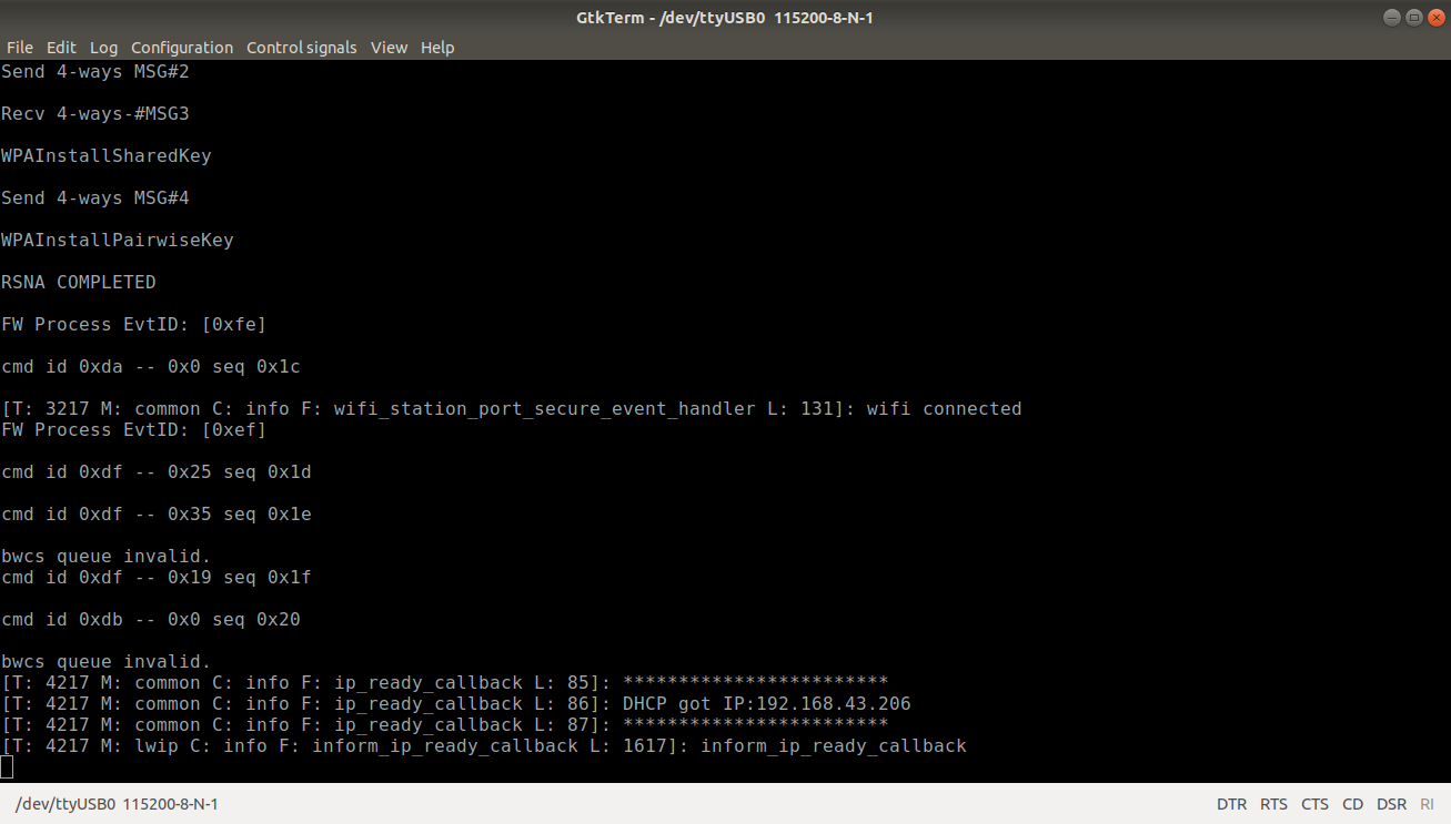
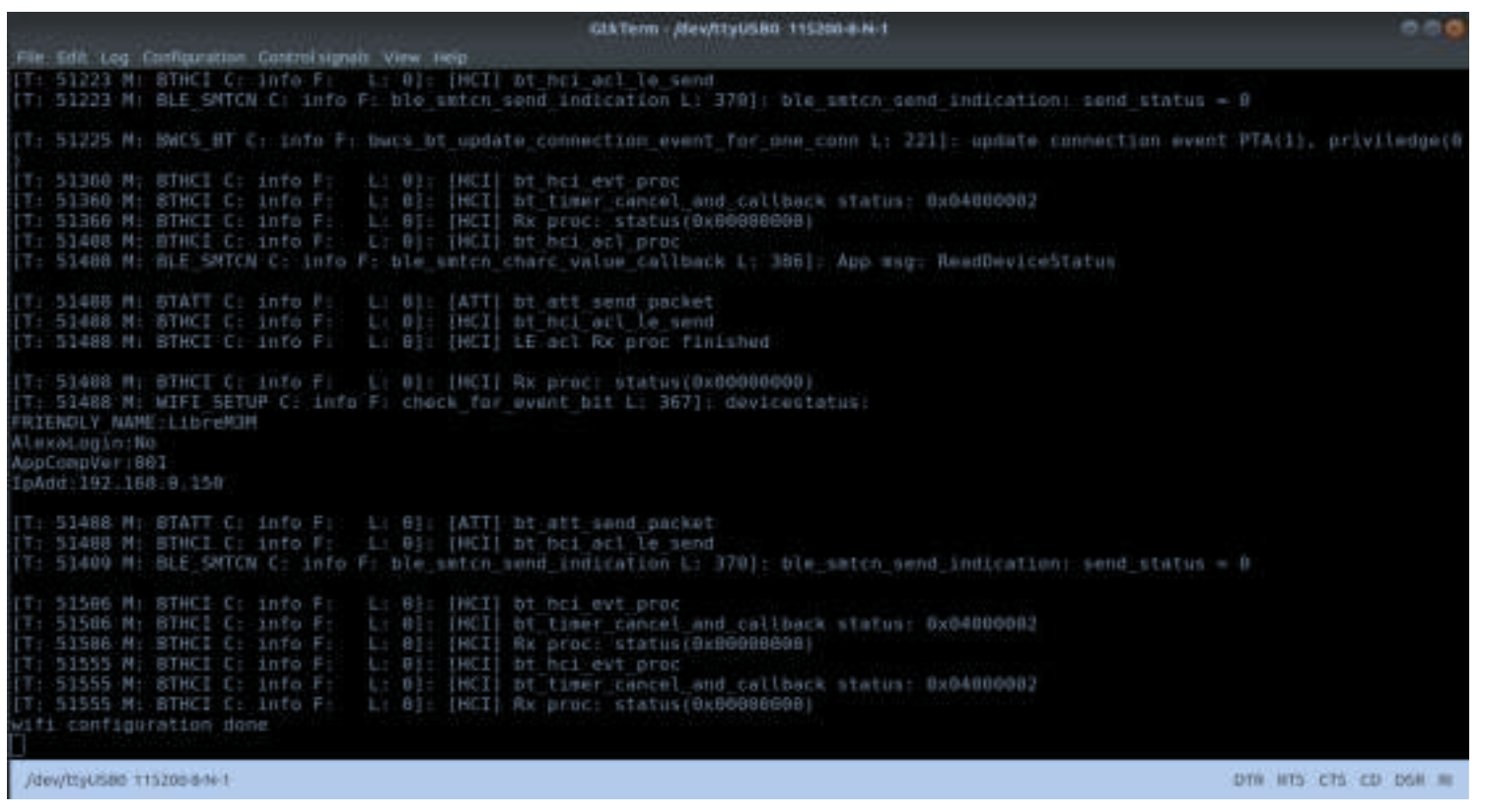
The example output is as displayed below:
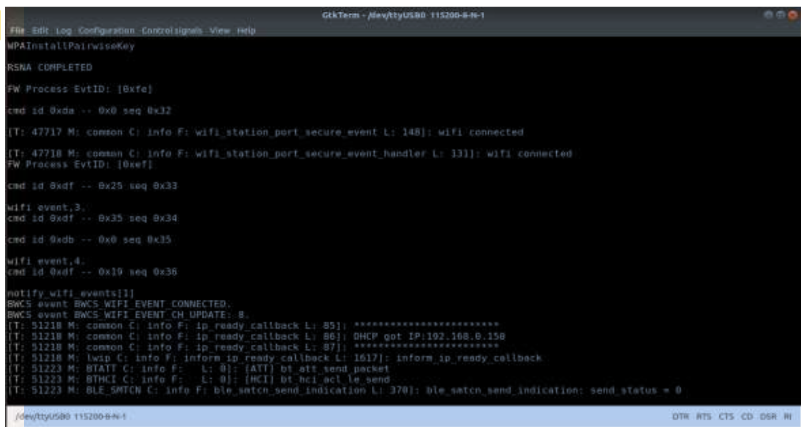
Example output screen:
This project demonstrates the AWS Publish Subscribe Example project of MAVID-3M_EVK.
This application is a simple demonstration program which shows how to use the AWS IoT APIs and start a service running AWS IoT MQTT client.
This application explain user to how to:
Find the AWS_Publish_Subscribeexample project at "<sdk_root>/project/aw7698_evk/apps/ AWS_Publish_Subscribe”.
Initialize CLI task to enable user input CLI command from UART port.
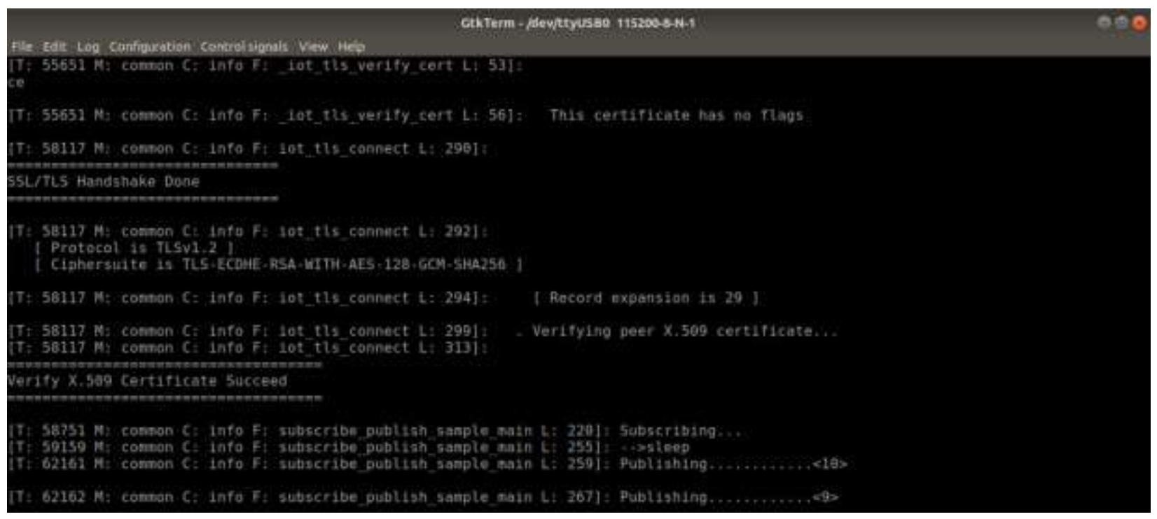
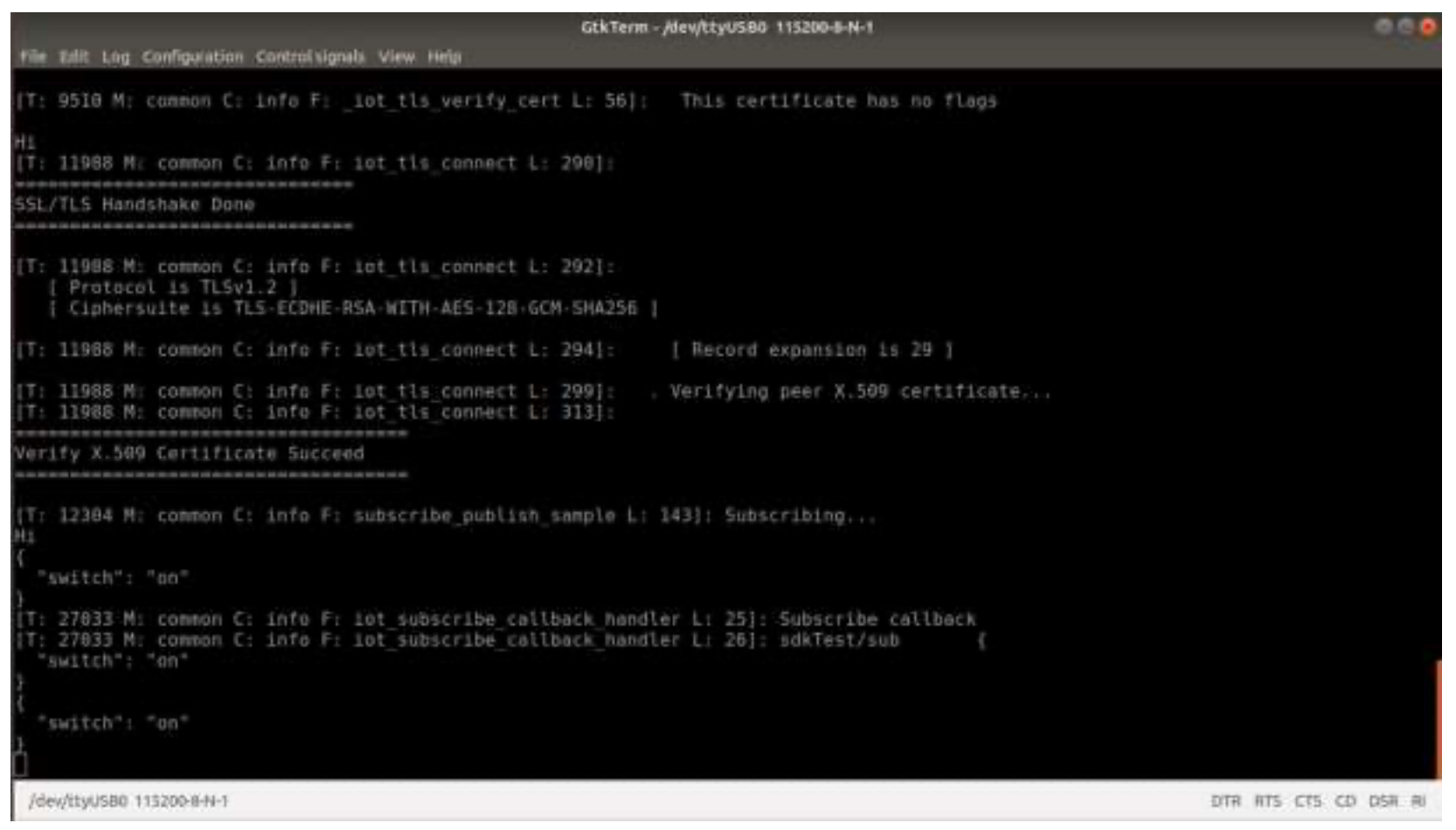
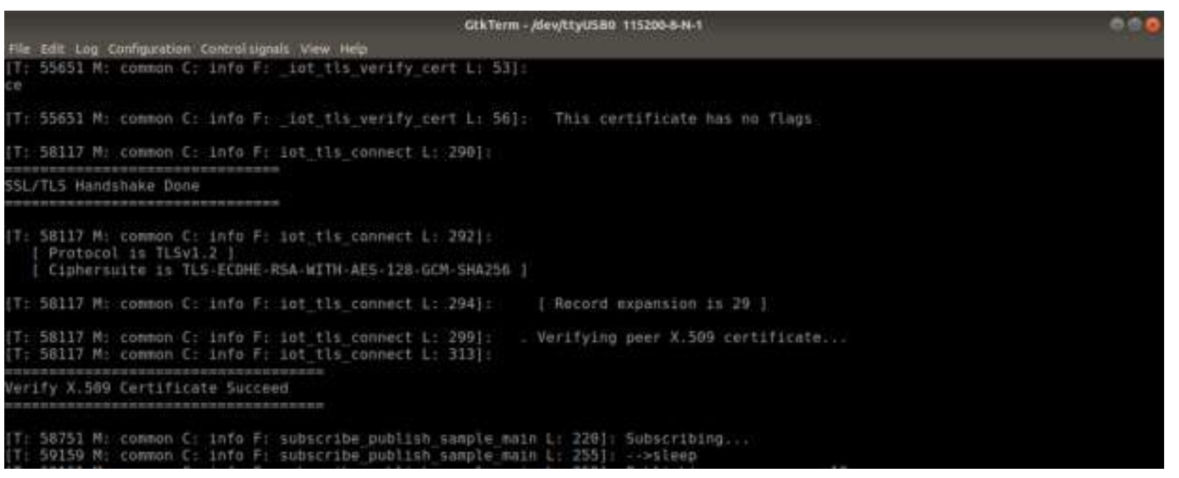
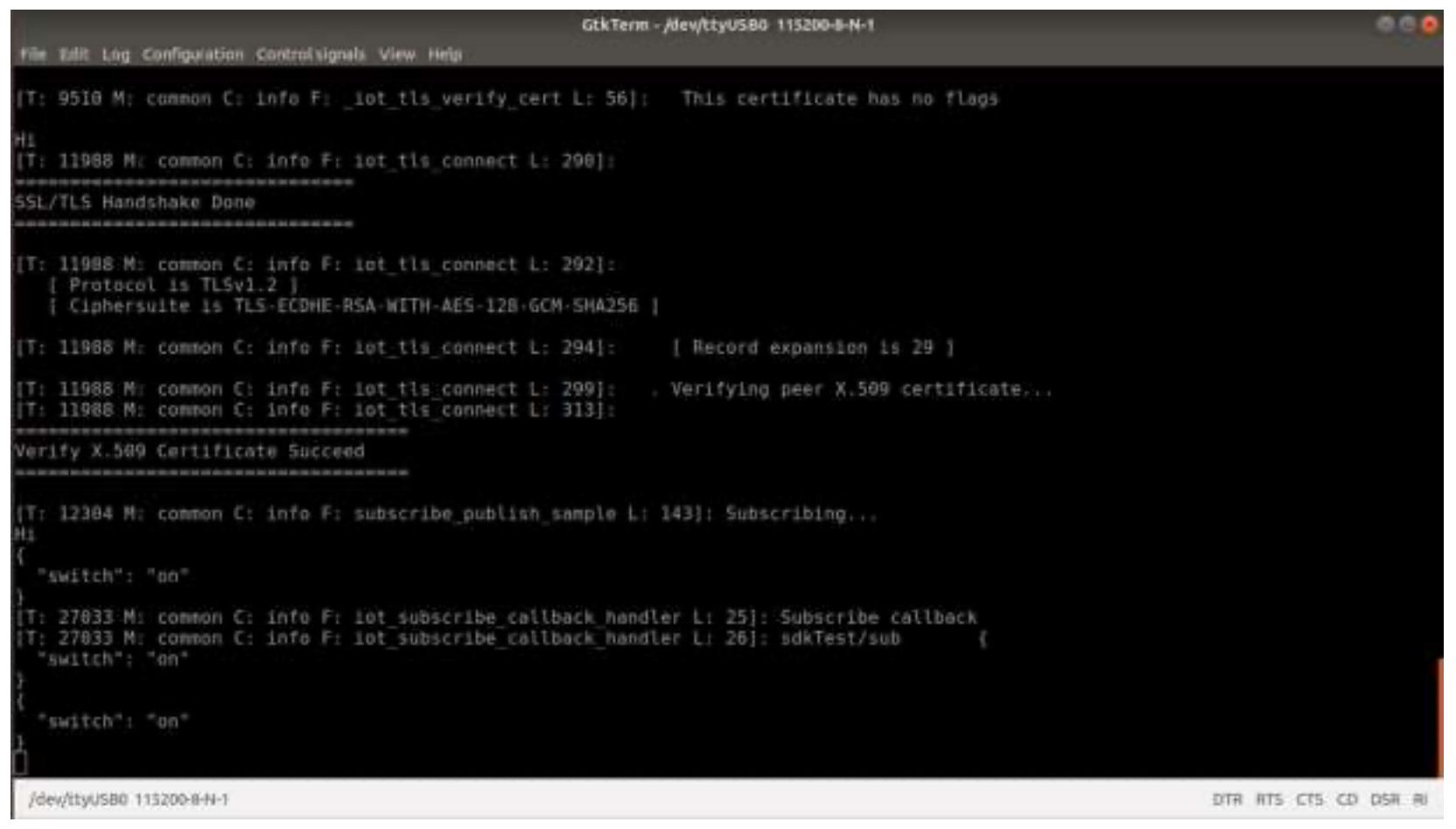
Run the Application, the below logs will be displayed:
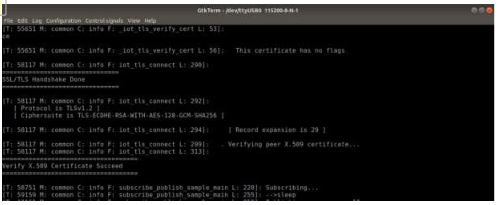
Output logs are as shown below:

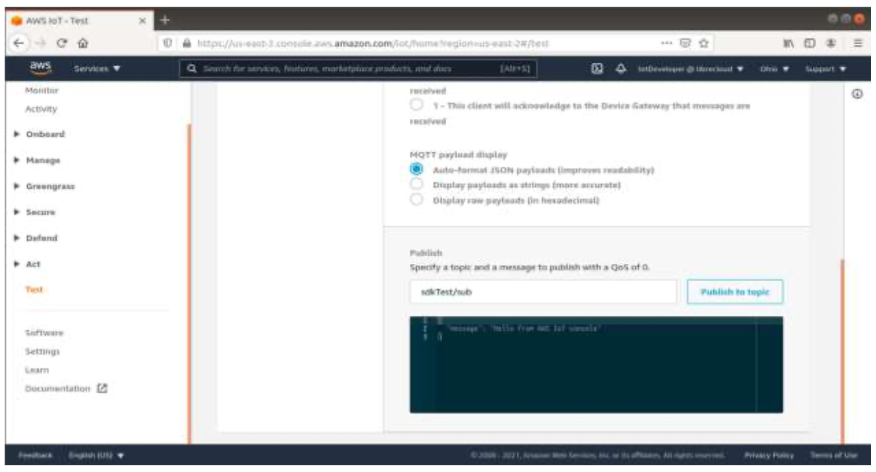
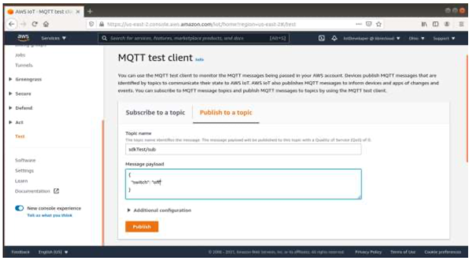
From AWS IoT console publish the topic from test as shown below:
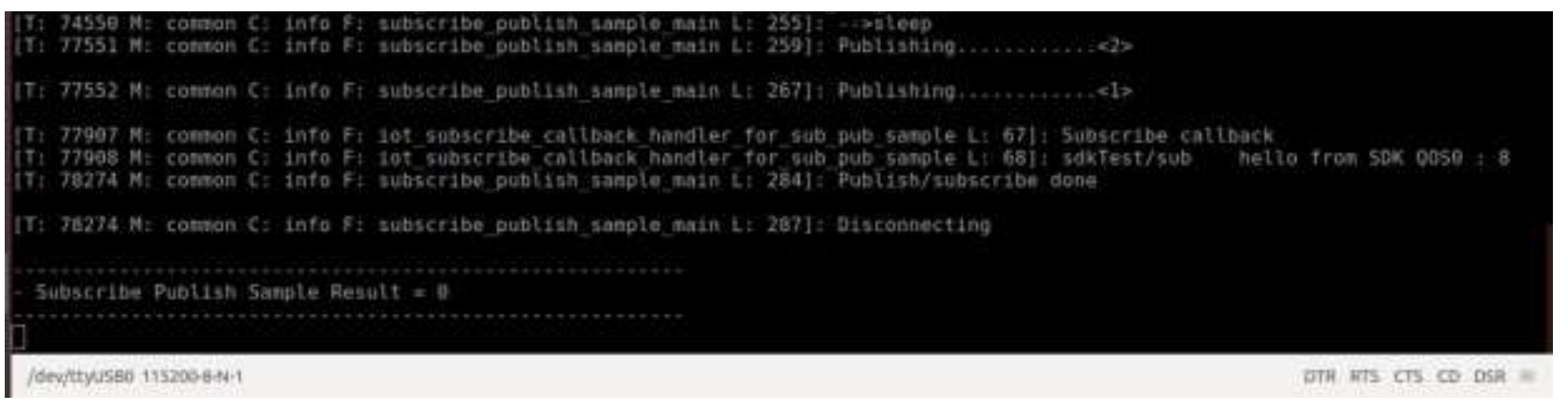
Run the Application, the below logs will be displayed:
Output logs are as shown below:
From AWS IoT console subscribe the topic from test as shown below:
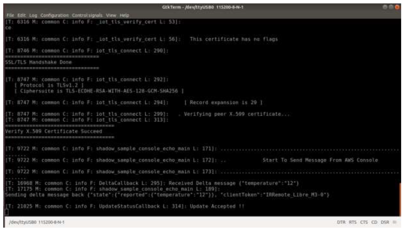
This project demonstrates the AWS SHADOW example project of the MAVID-3M_EVK. This application is a simple demonstration program which shows how to use the AWS IoT APIs and start a service running AWS IoT MQTT client.
This application explain user to how to:
Find the AWS_Shadow example project at "<sdk_root>/project/aw7698_evk/apps".
Initialize CLI task to enable user input CLI command from UART port.
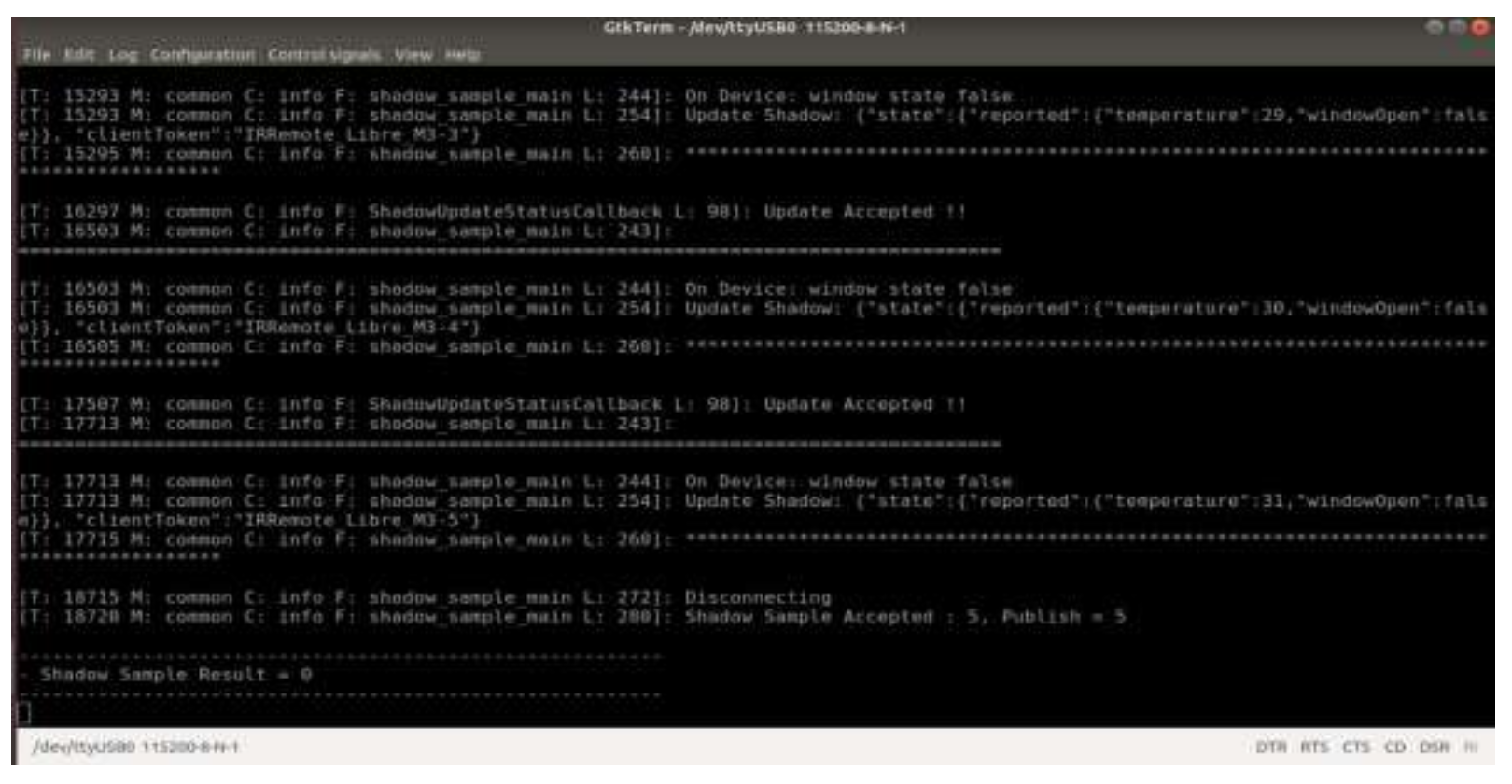
Run the Application, the below logs will be displayed:
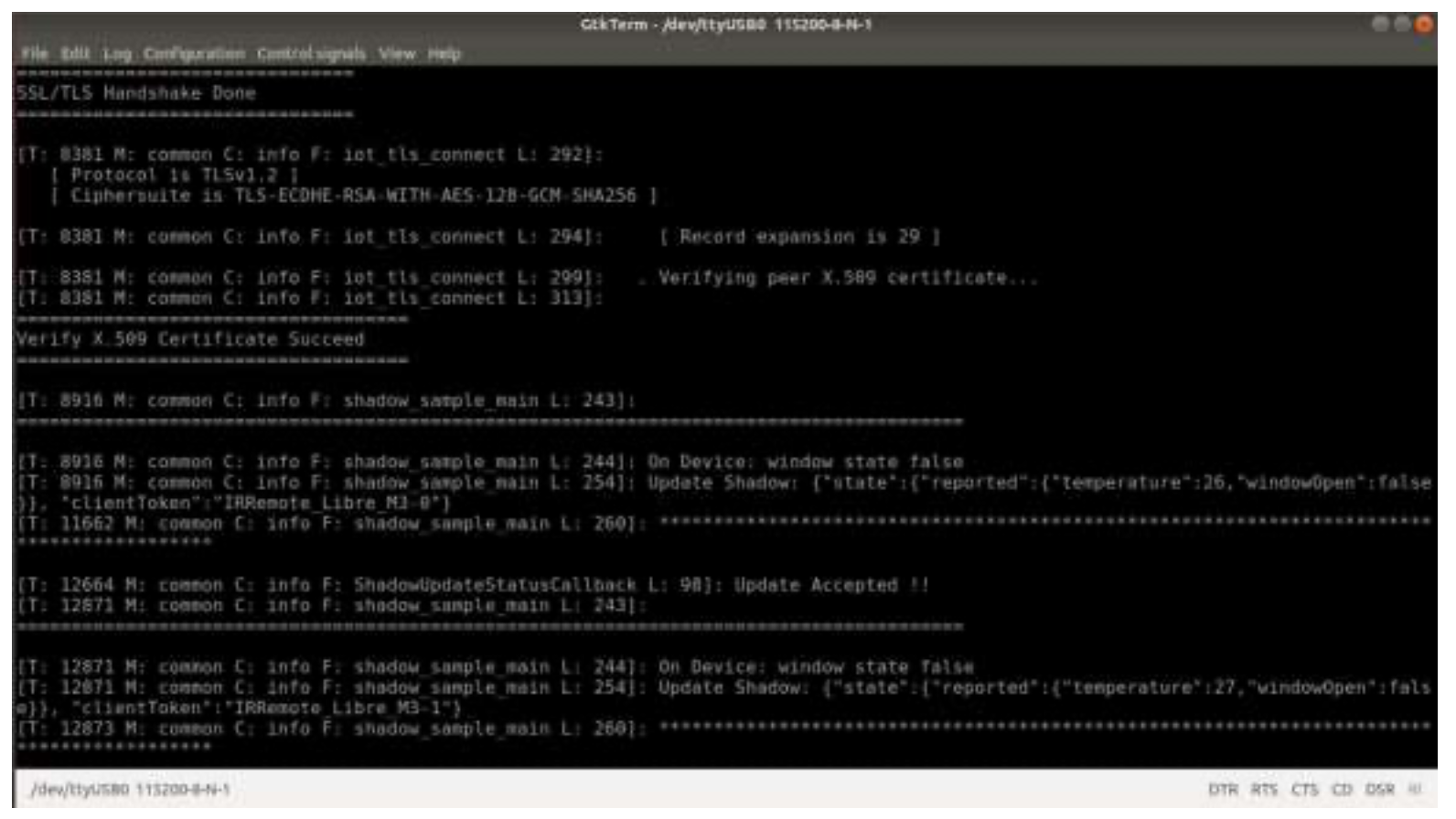
Final output screen:
From AWS IoT Console subscribe as per the command given below:
$aws/things/testThing/shadow/update/accepted
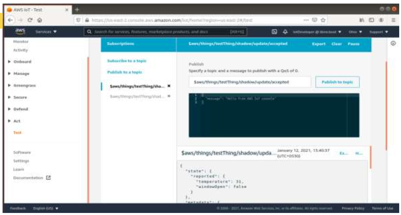
$aws/things/testThing/shadow/update/rejected

Run the Application, the below logs will be displayed:
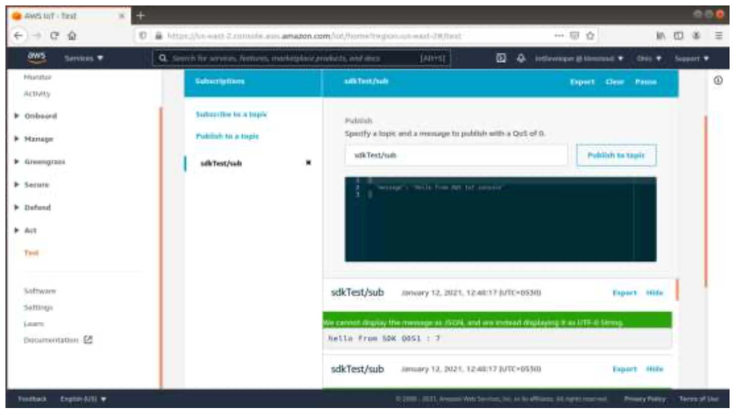
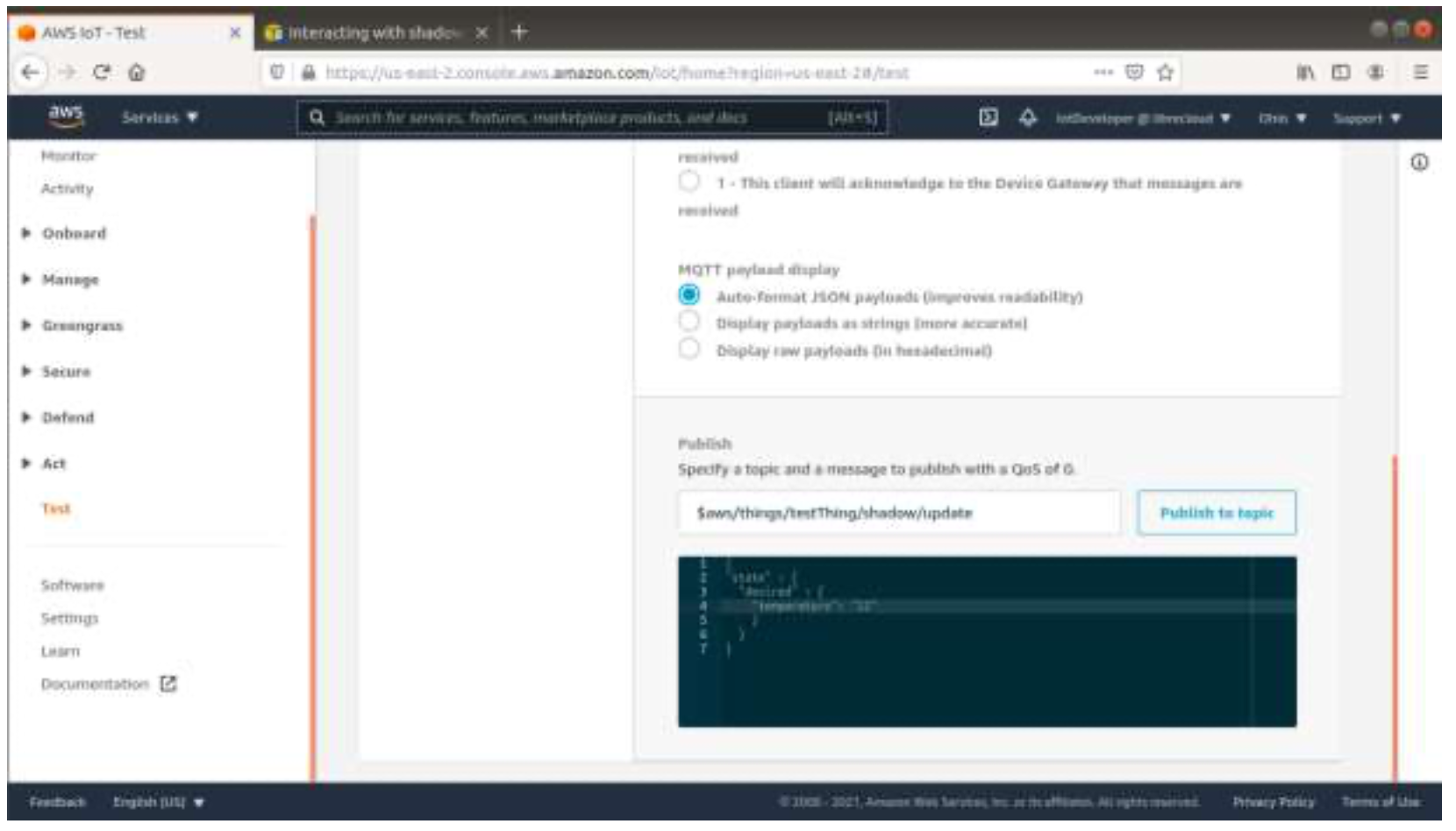
From AWS IoT Console publish the topic using the command given below:
$aws/things/testThing/shadow/update and enter the message format as given below:
Example 1:
{ “state” : { “desired” : { “temprature” : “12” “dooropen” : “false” } } }
Example 2:
{ "state": { "desired": { "switch": "on" } } }
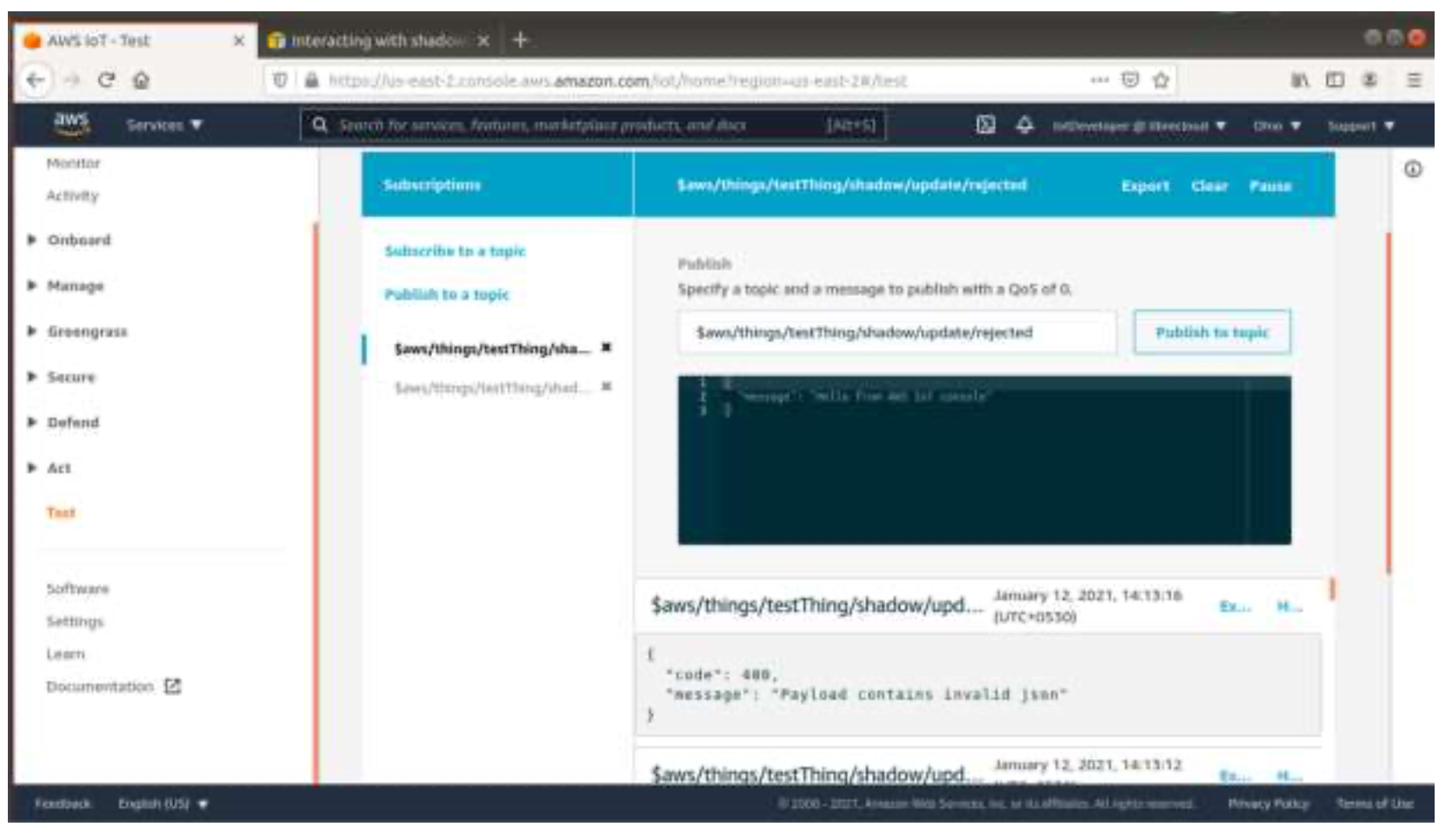
Subscribe the topic from AWS IoT Console side, it will provide the notification about the shadow update accepted or rejected:
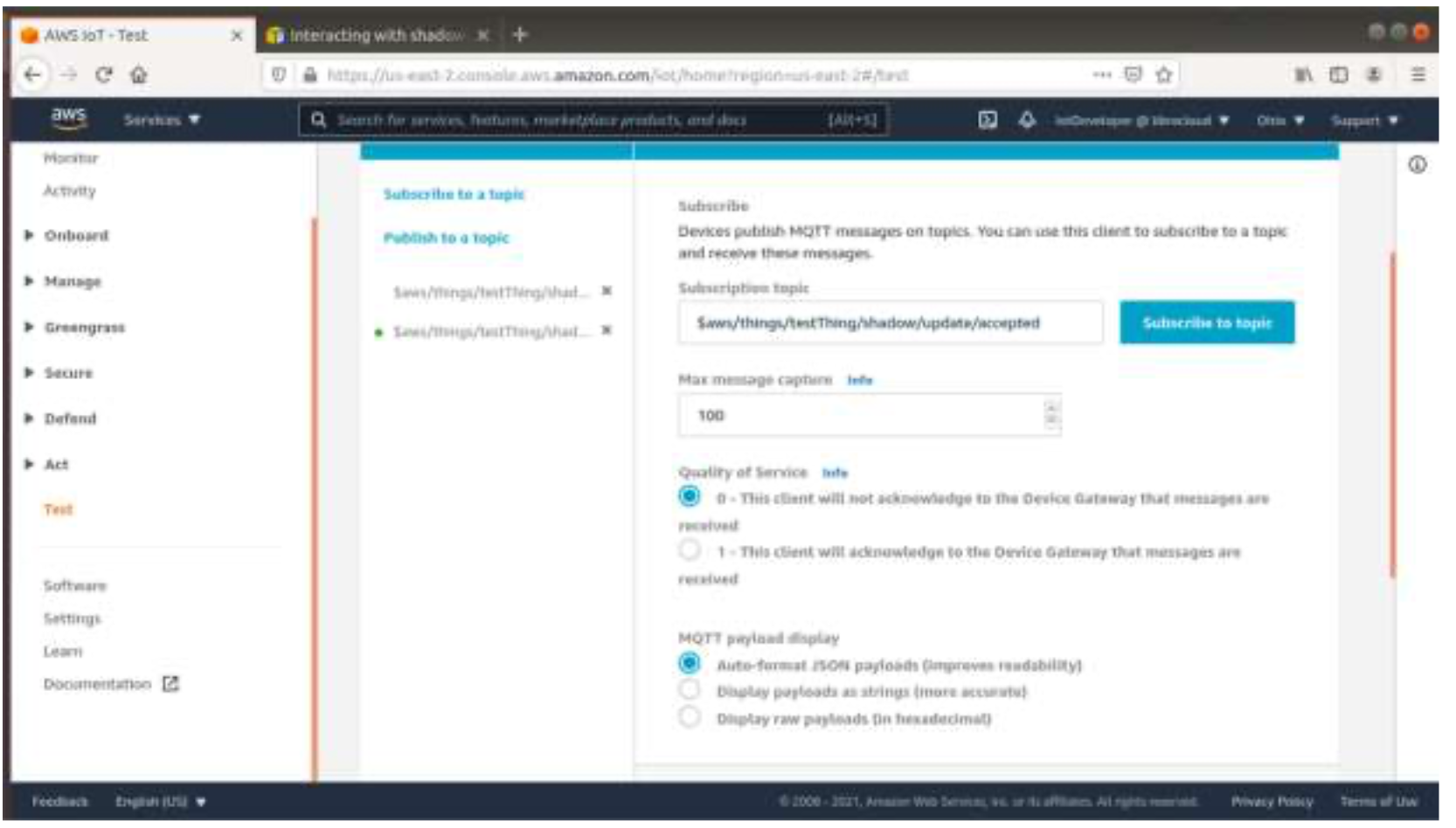
The below image indicates how to subscribe update for accepted:

The below image indicates subscribe update for rejected:
This project demonstrates the AWS IoT with LED interface project of MAVID-3M_EVK with AWS IoT APIs and start a service running AWS IOT MQTT client.
This application explain user to how to:
Find the AWS_iot_Subscribe_led example project at "<sdk_root>/project/aw7698_evk/apps".</sdk_root>
Initialize cli task to enable user input cli command from UART port.
Publish as INTEGRATION_TEST_TOPIC for AWS_IOT_MY_THING_NAME topic and send a message as a payload to turn ON and turn OFF the LED using AWS IoT console as shown below.
Payload turn ON screen:

Payload turn OFF screen:
Subscribe the Topic:
Run the Application, the below logs will be displayed:
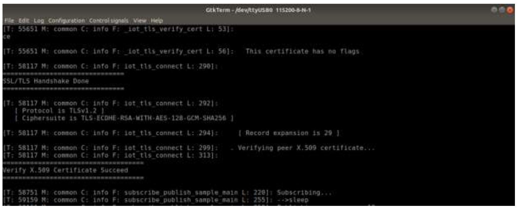
Final output screen:
This project demonstrates control of LED using Alexa Voice. It uses Alexa Voice service and AWS Cloud services (IoT Core, Alexa Smart Home Skills, etc.) to control a LED light using voice commands.
Find the avs_ledcontrol example project from "<sdk_root>/project/aw7698_evk/apps".

Run the Application, the below logs will be displayed:
Final output screen:
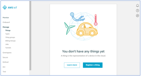
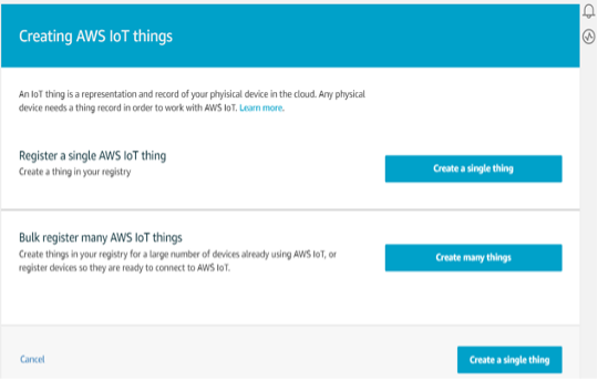
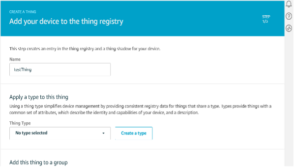
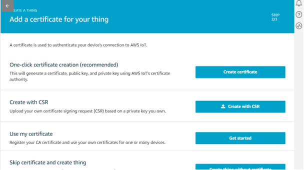
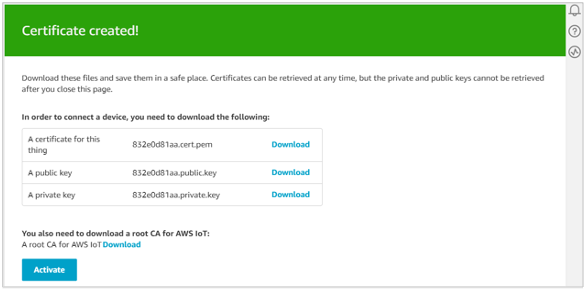
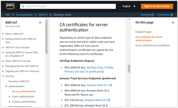
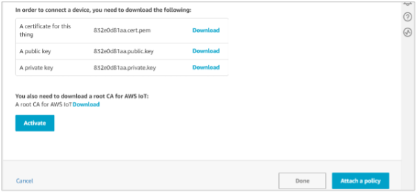
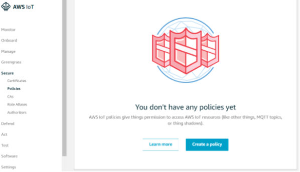
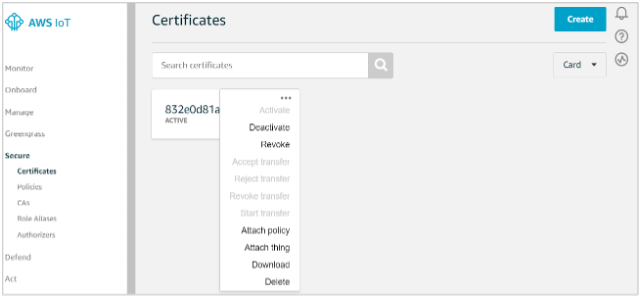
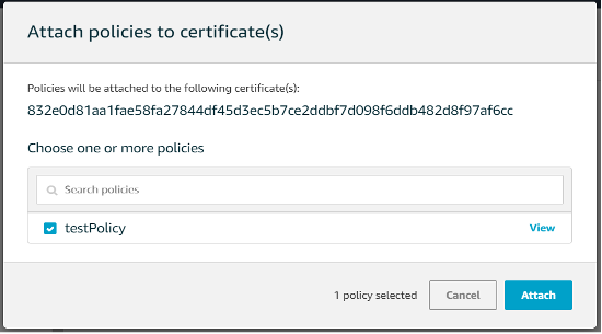
Follow the steps to provision the device on AWS management console. This includes creating IoT thing, generating certificates and policies, attaching policies and certificates to the IoT thing.
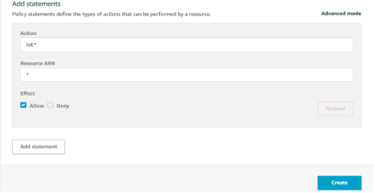
{ "Version": "2012-10-17", "Statement": [ { "Effect": "Allow", "Action": "iot:*", "Resource": "*" } ] }
This policy grants unrestricted access for all IoT operations and is to be used
only in a development environment. For non-dev environments, all devices
in your fleet must have credentials with privileges that authorize intended actions
only, which include (but not limited to) AWS IoT MQTT actions such as publishing
messages or subscribing to topics with specific scope and context. The specific
permission policies can vary for your use cases. Identify the permission policies that
best meet your business and security requirements. For sample policies,
refer to
https://docs.aws.amazon.com/iot/latest/developerguide/example-iot-policies.html
Also refer to
https://docs.aws.amazon.com/iot/latest/developerguide/security-bestpractices.html

This section explains the process of setting up AWS cloud infrastructure required for Voice based sample applications. This includes setting up of reference cloud, deployment of a Smart Home skill and configuring the IoT.
Pre-requisites:
This section walks through the usage of AWS CDK (Cloud Development Kit) for deploying AWS services such as AWS Lambda, AWS IoT Core and AWS Cognito.
Please follow here on how to run cdworkshop_stack.py python code given in <sdk_root>/aws_infrastructure directory to deploy the necessary infrastructure as per the reference architecture for voice-based sample application provided in MAVID-3M SDK.
Find test.json and my-lambda-handler.zip files from <sdk_root>/aws-infrastructure and add it into cdkworkshop directory, which is created for new project in CDK
workshop.Replace cdworkshop_stack.py file with cdworkshop_stack.py file given in <sdk_root>/aws-infrastructure, and
Add this to setup.py file:
install_requires=[
"aws-cdk.core==1.107.0",
"aws-cdk.aws_iam==1.107.0",
"aws-cdk.aws_sqs==1.107.0",
"aws-cdk.aws_sns==1.107.0",
"aws-cdk.aws_sns_subscriptions==1.107.0",
"aws-cdk.aws_s3==1.107.0",
//lines to Add
"aws-cdk.aws_iot==1.107.0",
"aws-cdk.aws_cognito==1.107.0",
"aws-cdk.aws_dynamodb==1.107.0",
"aws-cdk.aws_lambda==1.107.0",
"aws-cdk.aws_apigateway==1.107.0",
]
On successful deployment, user should be able to see the below AWS services deployed in his/her account:
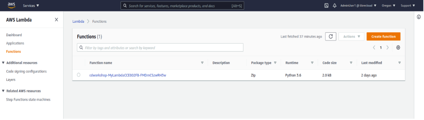
Figure 5.1-1: AWS Lambda
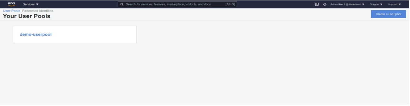
Figure 5.1-2: AWS Cognito
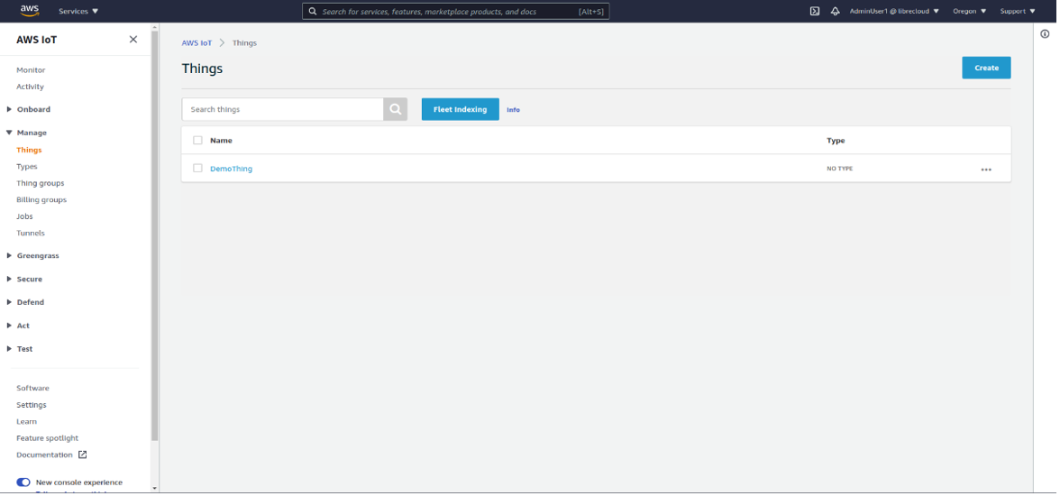
Figure 5.1-3: AWS IoT Things
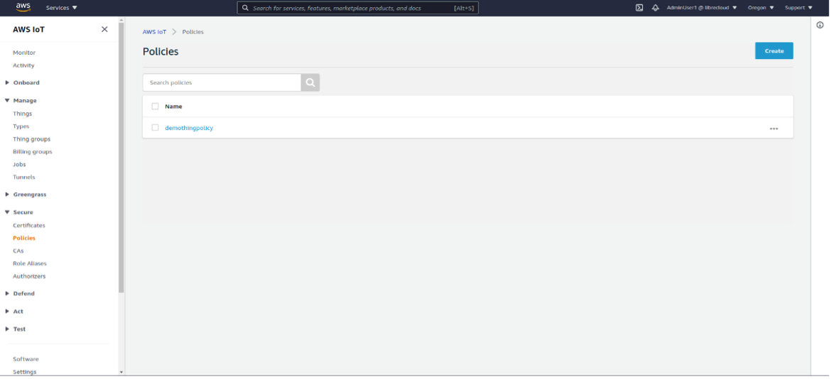
Figure 5.1-4: AWS IoT Policies
To create smart home skill, follow here
Configuring Smart Home Skill:
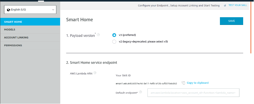
Figure 5.2-1: Smart Home Screen
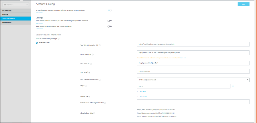
Figure 5.2-2: Smart Home Skill Console
.png)
Figure 5.2-3: AWS Lambda
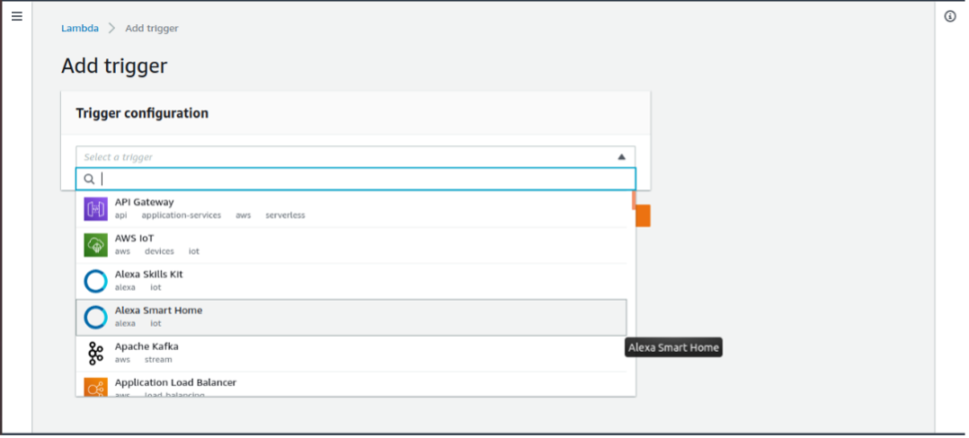
Figure 5.2-4: Add Trigger Screen

Figure 5.2-5: Add Trigger Screen
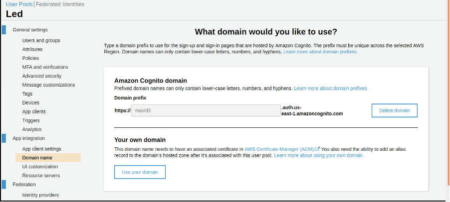
Figure 5.2-6: AWS Cognito Screen

Figure 5.2-7: AWS Cognito Screen
In Signout URLs: Append /logout to the domain name that was copied in step 6
Example: https://mavid3.auth.us-east-1.amazoncognito.com/logout
Under Allowed OAuth Scope tick/select the openid checkbox:
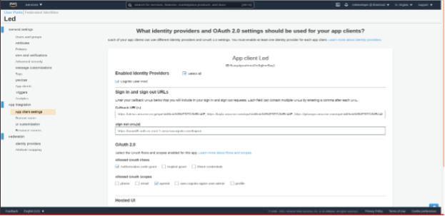
Figure 5.2-8: App Client Settings
Fill the above details as shown below:
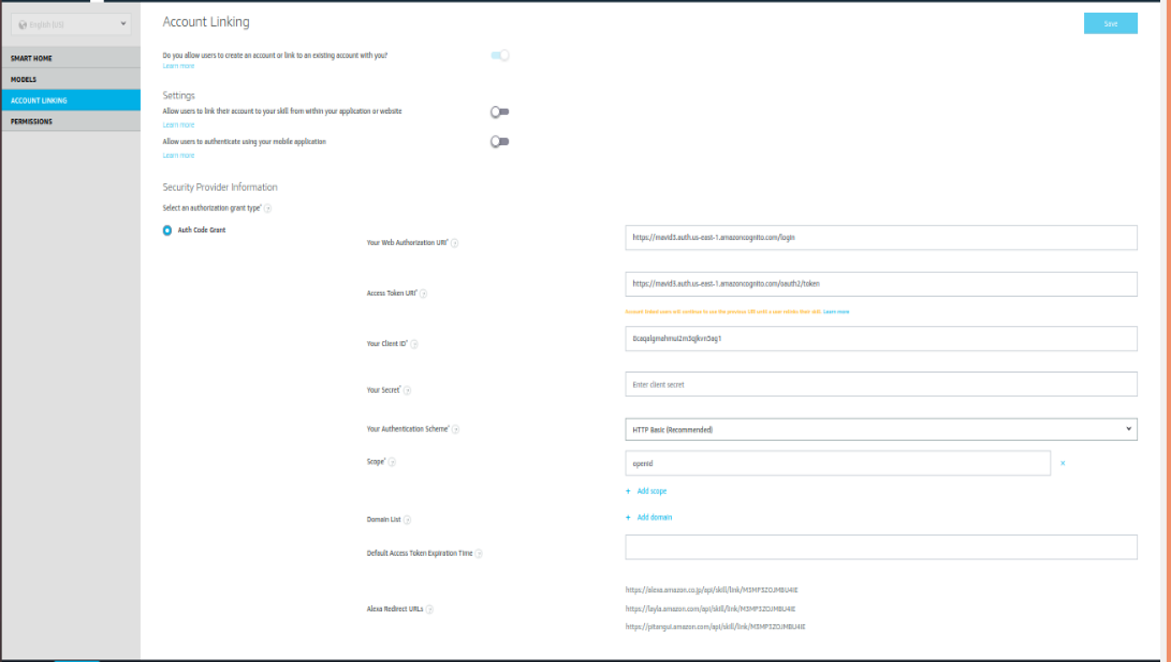
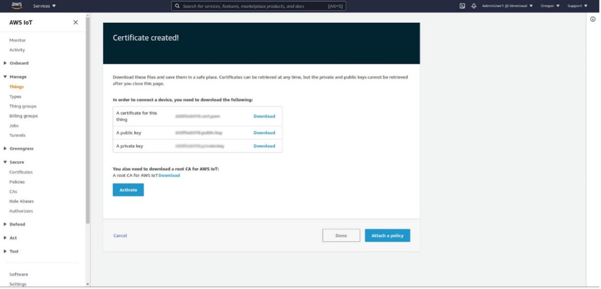
Figure 5.3-1: Attach a Policy
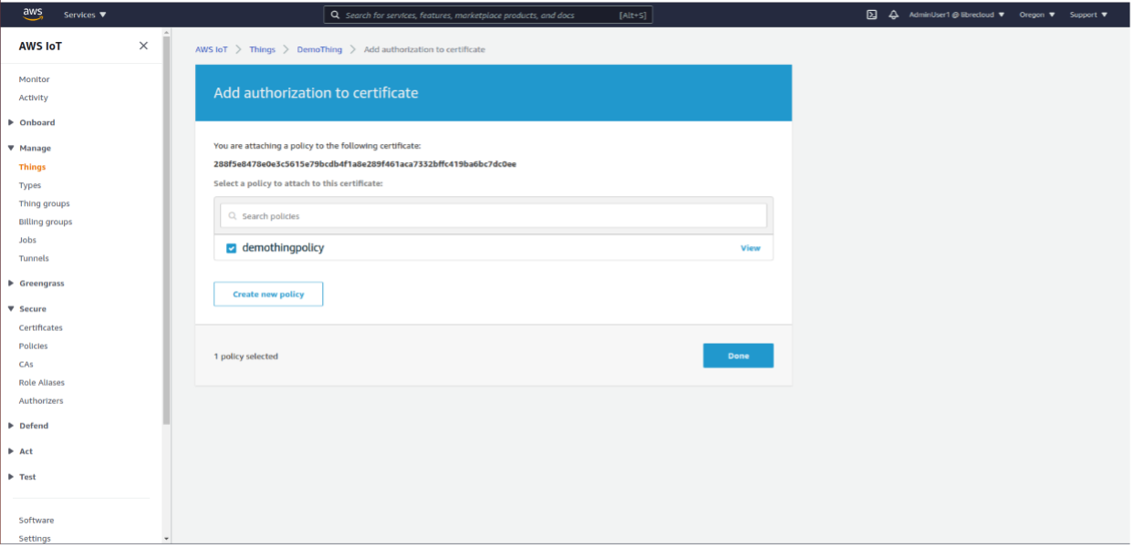
Figure 5.3-2: Add Authorization
Follow Us


Subscribe
Get in Touch

Security Ι © 2020 Libre Wireless Technologies, Inc.